Sunday, October 30, 2011
Open Shortest Path First – OSPF
1.Introduction to OSPF
OSPF is an IGP that routes packets
within a single AS or domain.
OSPF is a link-state routing protocol
and uses link-state advertisements (LSAs) to describe about network
topology. Each router gerenates LSAs describe about the network it
sees and floods the LSAs throughout the network. At the end, each
router has a link-state database (LSDB) that describes about the same
topology.
Once the router complete knows the
network topology, it runs the SPF (based on Djiktra algorithm)
calculation to determine the shortest path to each destination. The
calculation results a pair of destination/next-hop that are placed
into routing table. This calculation is performed independently on
each router.
OSPF runs directly over IP, using IP
protocol port 89. It does not use a transport layer protocol such as
TCP or UDP.
Each router has a router ID that
distinguishes a router with the rest. This router ID is unique.
Router ID is a 32-bit number written in dotted decimal notation that
looks like IP address. Router ID is typically a lo0 address.
OSPF devides each AS into one or more
segments called areas. Each area is a set of networks and hosts that
are administrative grouped together.
To exchange information between areas,
OSPF uses area border routers (ABRs) which are connected to two or
more areas.
ABRs run a separate SPF calculation and
maintain a separate link-state database for each area to which they
connected. ABRs summarize link-state information from one area
before passing to the next, which increase the overall stability for
network.
On each multiaccess network, OSPF
elects a designated router (DR) that establishes the adjacencies with
all router in network. DR election based on the priority which is a
number between 0 and 255. DR is a router with the highest priority
number. If two routers with equally priority number, the one with
lower router ID is selected. It also has a backup designated router
(BDR).
OSPF defines some types of area. The
core of an OSPF network is the backbone area, which is area 0
(0.0.0.0). All the ABRs attached to area 0.
2.Terminologies
2.1.Link state advertisements – LSAs
Each router maintains a database called
link-state database (LSDB), containing the lastest received LSAs. A
separate LSDB is maintained for each area connected to the router.
2.1.1. LSA operation
Each LSA is numbered with a sequence
number and a timer is run to age out old LSAs. By default, it is 30
minutes.
When a LSA received, it is compared
with LSDB. If it is new, it is added to the LSDB and SPF algorithm is
run.
If it is from a router ID that is
already in the database. The sequence number is compared and older
LSAs are discarded. If it is a new LSA, it is incorporated into LSDB
and SPF algorithm in run. If it is an older LSA, the newer LSA will
be sent back to the one which sent the old LSA.
OSPF sequence number is 32 bits. This
sequence number is changed whenever:
-LSA changes because a route is added
or deleted
-The LSA ages out. (LSA updates are
flooded every 30 minutes, even if nothing happens)
2.1.2. LSA types
OSPF uses different types of LSAs to
advertise different types of routes, such as external or internal
routing domain.

2.2.OSPF Operation
OSPF uses several differents type of
packets to establishe neighboring and maintains the routing
information.
2.2.1.OSPF packets
OSPF uses 5 packet types. It does not
use TCP or UDP for transmitting. It runs directly over IP port 89
using an IP header. 5 packet types:
-Hello: identifies neighbors and
serves as a keepalive
-Link State request (LSR): request for
a Link state update (LSU). Contains the type of LSU request and the
ID of router requesting it.
-Database Description (DBD): A summary
of LSDB, including RID and sequence of LSA in the LSDB
-Link state update (LSU) : contains a
full LSA entry. An LSA includes topology information. One LSU can
contain multiple LSAs.
-Link state acknowledgement (LSAck) :
Acknowledges all the OSPF packets (except Hellos).
OSPF traffic is multicass to either of
two addresses: 224.0.0.5 for all OSPF routers and 224.0.0.6 for OSPF
Drs.
2.2.2.OSPF Neighbor relationships
OSPF routers send periodic multicast
packet to introduce themselves to other router on link. They become
neighbors when they see their own router ID number included in the
neighbor field of the Hello from another router. And two routers must
be in a same subnet for a neighbor relationship to be performed.
Certain parameters in Hello packet must
match for two routers to become neighbors. They include:
-Hello/dead timers
-Area ID
-Authentication type and password (if
set)
-stub area flag
OSPF routers can be neighbors without
being adjacent. Only adjacent neighbors exchange routing updates and
synchronize their databases. On a point-to-point network, the
adjacent is established directly when they can communicate. On
multiaccess link, OSPF routers establishe adjacent with DR and BDR
Hello also serves as keepalives. A
neighbor is considered lost if no Hello packets received within four
Hello periods (dead timer). The default Hello/dead timers:
-10 seconds/40 seconds for LAN and
point-to-point interfaces
-30 seconds/120 seconds for
nonbroadcast multiaccess interfaces.
2.2.3.Establishing neighbors and
exchanging routes
The process to establishe the neighbors
and route exchange between two routers:
Step1: Down state: OSPF process not yet
started, no Hellos sent
Step2: Init state: router sends Hello
packets out all OSPF interfaces
Step3: Two-way state: routers receive
Hellos from another router that contains its own router ID in
neighbor list. All other required elements match, so routers can
become neighbors.

When step3 ends, the neighbors are
established. The following steps below refer to the exchanging
routes.
Step4: Exstart state: If router become
adjacent (exchang routes), they determines which one starts the
exchange process. In this case, which router with higher router ID
will start the process.
Step5: Exchange state: routers exchange
the DBDs that describe the local databases.
Step6: Loading state: Each router
compares the DBD received to the local contents. It then sends the
LSR for missing or outdated LSAs. Each LSR will be responded with a
LSU. Each LSU is acknowledged.
Step7: Full state: the LSDB has been
synchronized with the adjacent neighbor.

3.Configuring OSPF
3.1. Backbone/single area (area 0)
In this section, I will introduce how to configure OSPF in single-area (area 0).
Using this topology to illustrate:

Configurations:
=====
R1:
=====
cuong@Jun1# show protocols
ospf {
area 0.0.0.0 {
interface lo0.0;
interface em1.0;
interface em2.0;
}
}
[edit]
==
R2
==
cuong@Jun2# show protocols
ospf {
area 0.0.0.0 {
interface lo0.0;
interface em1.0;
interface em2.0;
}
}
==
R3
==
cuong@Jun3# show protocols
ospf {
area 0.0.0.0 {
interface lo0.0;
interface em1.0;
interface em2.0;
}
}
Using “show ospf
route” to determine the ospf routes
cuong@Jun1> show ospf route
Topology default Route Table:
Prefix Path Route
NH Metric NextHop Nexthop
Type Type
Type Interface Address/LSP
192.168.2.1 Intra Router
IP 1 em1.0 10.0.0.6
192.168.3.1 Intra Router
IP 1 em2.0 11.0.0.6
10.0.0.0/24 Intra Network
IP 1 em1.0
11.0.0.0/24 Intra Network
IP 1 em2.0
12.0.0.0/24 Intra Network
IP 2 em1.0 10.0.0.6
em2.0 11.0.0.6
192.168.1.0/24 Intra Network
IP 0 lo0.0
192.168.1.1/32 Intra Network
IP 0 lo0.0
192.168.2.0/24 Intra Network
IP 1 em1.0 10.0.0.6
192.168.2.1/32 Intra Network
IP 1 em1.0 10.0.0.6
192.168.3.0/24 Intra Network
IP 1 em2.0 11.0.0.6
192.168.3.1/32 Intra Network
IP 1 em2.0 11.0.0.6
To determine which
routes that router has learned from OSPF, check the unicast routing
table:
cuong@Jun1>
show route protocol ospf table inet.0
inet.0: 14
destinations, 14 routes (14 active, 0 holddown, 0 hidden)
+ = Active
Route, - = Last Active, * = Both
12.0.0.0/24
*[OSPF/10] 00:21:54, metric 2
> to 10.0.0.6 via em1.0
to 11.0.0.6 via em2.0
192.168.2.0/24
*[OSPF/10] 00:22:46, metric 1
> to 10.0.0.6 via em1.0
192.168.2.1/32
*[OSPF/10] 00:22:46, metric 1
> to 10.0.0.6 via em1.0
192.168.3.0/24
*[OSPF/10] 00:21:54, metric 1
> to 11.0.0.6 via em2.0
192.168.3.1/32
*[OSPF/10] 00:21:54, metric 1
> to 11.0.0.6 via em2.0
224.0.0.5/32
*[OSPF/10] 00:50:42, metric 1
MultiRecv
3.2.Configuring
authentication
Authentication is
required if you want to prevent the spoofing in neighbor establish
process.
==
R1
==
[edit]
cuong@Jun1# show protocols ospf area
0.0.0.0
interface lo0.0;
interface em1.0 {
authentication {
md5 1 key
"$9$H.fz9A0hSe36SevW-dk.P"; ## SECRET-DATA
}
}
interface em2.0 {
authentication {
md5 1 key
"$9$H.fz9A0hSe36SevW-dk.P"; ## SECRET-DATA
}
}
==
R2
==
[edit protocols ospf area 0.0.0.0]
cuong@Jun2# show
interface lo0.0;
interface em1.0 {
authentication {
md5 1 key
"$9$xnD-b2ZUH5Qn4aQn/CB17-V"; ## SECRET-DATA
}
}
interface em2.0 {
authentication {
md5 1 key
"$9$oJZDk5Qnp0I.P0IEcvMaZU"; ## SECRET-DATA
}
}
==
R3
==
[edit protocols ospf area 0.0.0.0]
cuong@Jun3# show
interface lo0.0;
interface em1.0 {
authentication {
md5 1 key
"$9$hD7yeWNdsJGiLxGik.zFcyl"; ## SECRET-DATA
}
}
interface em2.0 {
authentication {
md5 1 key
"$9$rNkKWxbs4Di.Ndi.P56/lKM"; ## SECRET-DATA
}
}
Wednesday, October 26, 2011
Overviews of Routing Information Protocol – RIP
1.Overview of RIP
RIP is a standard protocol, but in this post, i want to introduce some knowledges relate to Junos OS
RIP is a dynamic routing protocol operates within a Routing Domain (IGP). It uses the distance vector algorithm to determine the best route to a destination. The distance is measured in hops, which is a number of router that a packet must pass to reach the destination. The best route is the route with the lowest of hops. In routing table, RIP maintains two informations:
RIP v1 routers exchange their routing information by broadcasting RIP route information every 30 minutes. RIP uses UDP packets for all transactions with port number 520
2.Routing loops in RIP
A problem of the most dynamic routing protocol is routing loop that provides the incorrect routing information. RIP uses two methods to control this problem:
-Split horizon: when a device receives the route advertisement on an interface, it will not readvertise back that information on the earlier interface.


RIP is a standard protocol, but in this post, i want to introduce some knowledges relate to Junos OS
RIP is a dynamic routing protocol operates within a Routing Domain (IGP). It uses the distance vector algorithm to determine the best route to a destination. The distance is measured in hops, which is a number of router that a packet must pass to reach the destination. The best route is the route with the lowest of hops. In routing table, RIP maintains two informations:
- IP address of the destination network
- and the hop count (metric) to that destination.
RIP v1 routers exchange their routing information by broadcasting RIP route information every 30 minutes. RIP uses UDP packets for all transactions with port number 520
2.Routing loops in RIP
A problem of the most dynamic routing protocol is routing loop that provides the incorrect routing information. RIP uses two methods to control this problem:
-Split horizon: when a device receives the route advertisement on an interface, it will not readvertise back that information on the earlier interface.
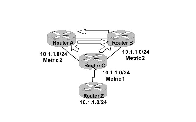
In the figure above, Router Z advertises route 10.1.1.0/24 to router C and increases 1 in the metric. At this
time, router C knows that the metric to reach to 10.1.1.0 is 1. And
router C does not advertise this information back to router Z since
it received from router Z. And so on, router A and B receive
information from router C and increase the metric by 1 and again, do
not advertise back to router C.
-Poison reverse: when a RIP device
knows a route is no longer connected or reachable, it will
advertises that route with an infinite value of metric (16). With
this information, each RIP device treats that route is unreachable
and never advertise information about that route.
Junos software default supports all
above functions.
3.Limitations of RIP
-RIP can be used only in a small
network. Because the infinite of hops are 16.
-RIPv1 only uses classful routing. It
can not handle the subnet and mask informations
-RIPv1 only uses plain-text password
authentication which can be easily sniffed in the insecured network.
4.RIPv2
RIPv2 was developed to increase the
security in RIP. It supports CIDR and MD5 authentication. The
limitation of 15 hops was remained.
By default, Junos RIP only listens to
RIP updates. The router does not advertise the updates until you tell
it to do. This is done by setting up the routing policy.
5.Configuring RIP on Junos OS
I use Junos Olive running on VMware to emulate in this guide
5.1.Basic RIP configuration
Diagram:

Configuration on each router:
[edit protocols rip]
cuong@Jun1# show
group rip-group { <- define a rip group
export rip-policy; <- a routing policy to advertise RIP information
neighbor em1.0; <- interfaces take part in the routing
neighbor lo0.0;
}
// routing policy allows rip advertises information
[edit policy-options]
cuong@Jun1# show
policy-statement rip-group {
from protocol [ rip direct ]; <- all rip/direct routes
then accept; <-- all routes after from statement are allowed
}
[edit protocols rip]
cuong@Jun2# show
group rip-group {
export rip-policy;
neighbor em1.0;
neighbor em2.0;
}
[edit protocols rip]
cuong@Jun3# show
group rip-group {
export rip-policy;
neighbor em1.0;
neighbor lo0.0;
}
Results in each router:
cuong@Jun1> show route protocol
rip
inet.0: 9 destinations, 10 routes (9
active, 0 holddown, 0 hidden)
+ = Active Route, - = Last Active, *
= Both
11.0.0.0/24 *[RIP/100]
00:06:53, metric 2, tag 0
> to 10.0.0.6
via em1.0
172.16.1.0/24 *[RIP/100]
00:06:02, metric 3, tag 0
> to 10.0.0.6
via em1.0
192.168.128.0/24 [RIP/100]
00:06:53, metric 2, tag 0
> to 10.0.0.6
via em1.0
224.0.0.9/32 *[RIP/100]
00:07:43, metric 1
MultiRecv
--
cuong@Jun2> show route protocol
rip
inet.0: 9 destinations, 10 routes (9
active, 0 holddown, 0 hidden)
+ = Active Route, - = Last Active, *
= Both
172.16.1.0/24 *[RIP/100]
00:06:26, metric 2, tag 0
> to 11.0.0.6
via em2.0
192.168.2.0/24 *[RIP/100]
00:08:01, metric 2, tag 0
> to 10.0.0.5
via em1.0
192.168.128.0/24 [RIP/100]
00:08:01, metric 2, tag 0
to 10.0.0.5
via em1.0
> to 11.0.0.6
via em2.0
224.0.0.9/32 *[RIP/100]
00:07:17, metric 1
MultiRecv
--
cuong@Jun3> show route protocol
rip
inet.0: 9 destinations, 10 routes (9
active, 0 holddown, 0 hidden)
+ = Active Route, - = Last Active, *
= Both
10.0.0.0/24 *[RIP/100]
00:07:36, metric 2, tag 0
> to 11.0.0.5
via em1.0
192.168.2.0/24 *[RIP/100]
00:08:23, metric 3, tag 0
> to 11.0.0.5
via em1.0
192.168.128.0/24 [RIP/100]
00:07:36, metric 2, tag 0
> to 11.0.0.5
via em1.0
224.0.0.9/32 *[RIP/100]
00:06:52, metric 1
MultiRecv
Testing routes
cuong@Jun1> ping 172.16.1.1
PING 172.16.1.1 (172.16.1.1): 56
data bytes
64 bytes from 172.16.1.1: icmp_seq=0
ttl=63 time=0.598 ms
64 bytes from 172.16.1.1: icmp_seq=1
ttl=63 time=1.002 ms
64 bytes from 172.16.1.1: icmp_seq=2
ttl=63 time=1.017 ms
^C
--- 172.16.1.1 ping statistics ---
3 packets transmitted, 3 packets
received, 0% packet loss
round-trip min/avg/max/stddev =
0.598/0.872/1.017/0.194 ms
5.2.Enabling
authentication
Using two commands
to set authentication on RIP routers
[edit protocols rip]
set authentication-type md5 <--
md5 is a type of authentication, it encrypts the plain-text password
[edit protocols rip]
cuong@Jun3# set authentication-key
juniper <-- juniper is a key
(password), used for all RIP routers in network.
Configuration on
each router:
cuong@Jun1# set rip
authentication-type md5
[edit protocols]
cuong@Jun1# set rip
authentication-key juniper
[edit protocols]
cuong@Jun1# show
rip {
authentication-type md5;
authentication-key
"$9$R2AcrvxNboJDWLJDikTQEcy"; ## SECRET-DATA
group rip-group {
export rip-policy;
neighbor em1.0;
neighbor lo0.0;
}
}
--
cuong@Jun2# set authentication-type
md5
[edit protocols rip]
cuong@Jun2# set authentication-key
juniper
[edit protocols rip]
cuong@Jun2# show
authentication-type md5;
authentication-key
"$9$fQ390BEevLApvLxNY25QF"; ## SECRET-DATA
group rip-group {
export rip-policy;
neighbor em1.0;
neighbor em2.0;
}
--
cuong@Jun3# set authentication-type
md5
[edit protocols rip]
cuong@Jun3# set authentication-key
juniper
[edit protocols rip]
cuong@Jun3# show
authentication-type md5;
authentication-key
"$9$0DAq1EyM87s2alK2aZU.mO1R"; ## SECRET-DATA
group rip-group {
export rip-policy;
neighbor em1.0;
neighbor lo0.0;
}
Monday, October 24, 2011
[Juniper] Cấu hình static routing trên Junos OS
[This video shows how to configure static routing on Junos OS]
Giới thiệu về static route tại đây
Video:
sau khi convert từ ogv sang avi để upload lên youtube thì video hơi nhanh một chút, mọi người thông cảm.
Giới thiệu về static route tại đây
Video:
sau khi convert từ ogv sang avi để upload lên youtube thì video hơi nhanh một chút, mọi người thông cảm.
Subscribe to:
Posts (Atom)